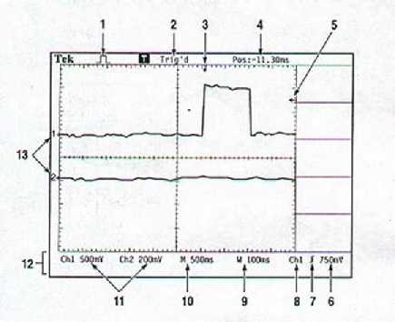
| 1. Icon display: | Sample mode Peak detect mode Average mode (See ACQUIRE SECTION) |
| 2. Trigger Status: | Displayed if there is a triggerable source or if the acquisition not working See TRIGGER CONTROL |
3. Horizontal trigger position on the waveform
4. Postion of the trigger position in reference to origin
5. Triggering level on the waveform
6. Triggering level shown in numeric value, volts
7. Icon for edge of triggering; rising or falling
8. Source of trigger
9. Windowed timebase setting
See HORIZONTAL CONTROL
10. Main timebase; in seconds per division
11. Channel 1 and 2 vertical scale factor, in volts per division
12. Display area for any temporary on-line messages
13. Markers indicating ground point for corresponding waveform